MicroPython Tutorial
Getting Started with MicroPython
- Building MicroPython for ESP32
- MicroPython: Input and Output
- Installing MicroPython for ESP8266 & ESP32
- MicroPython Libraries
- MicroPython: Motor Control
- MicroPython: Networking
- NodeMCU (ESP8266)
- MicroPython on the OHMC LoliBot
- WebREPL and WebPad
- MicroPython on the Witty Cloud
- MPY-TUT
- esptool.py
- esptool.py test cases README
- mpy-webpad
- WebREPL client for MicroPython
MicroPython on the Witty Cloud
The Witty Cloud Module
The Witty Cloud is a small, cheap development board available from many Ebay / AliExpress sellers. It consists of two boards sandwiched together
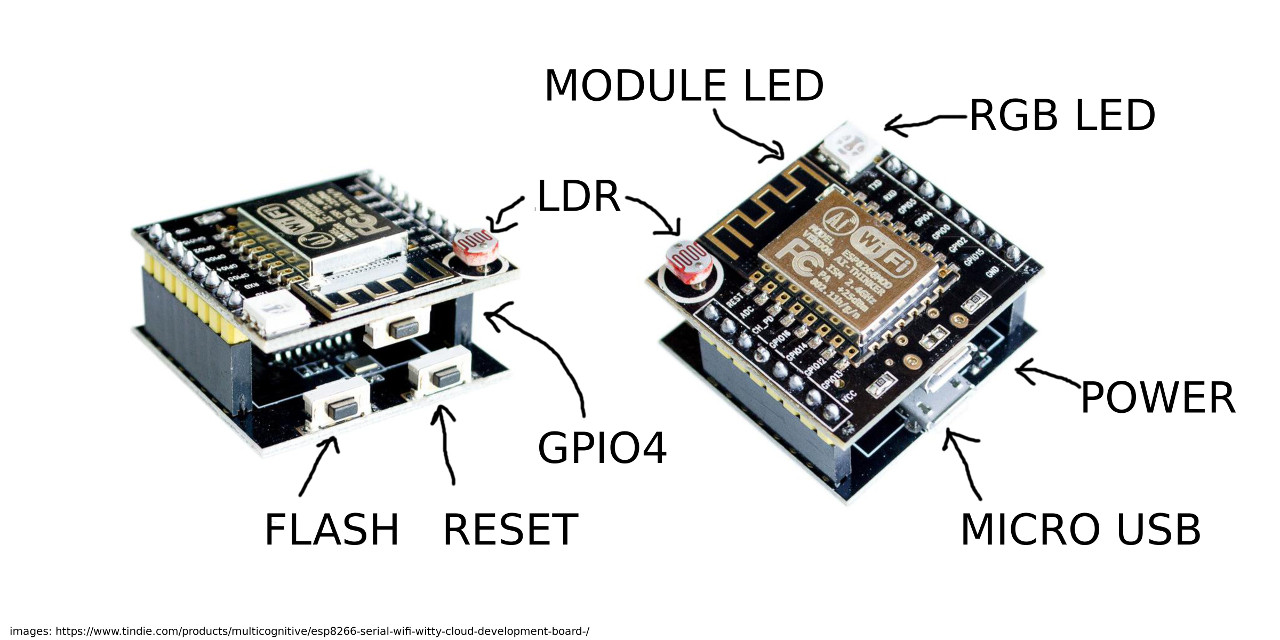
It is based around an ESP-12F module, which contains an ESP8266 processor, 4MB of flash memory, an oscillator and a small blue LED.
The upper board has the ESP-12F plus an RGB LED, a pushbutton, a light-dependent resistor (LDR) and (on the underside) a 3.3V regulator and a micro USB socket (power only).
The lower board has a USB to serial converter, an auto-reset circuit to put the ESP8266 into flash mode and couple more buttons.
The ESP8266 pins are connected as follows
| ESP8266 | Connection |
|---|---|
| RST | Reset button on lower board |
| GPIO0 | Flash button on lower board |
| GPIO1 | TXD from serial converter |
| GPIO2 | Blue LED on ESP-12F |
| GPIO3 | RXD from serial converter |
| GPIO4 | Button on upper board |
| GPIO5 | |
| GPIO12 | RGB LED (Blue) |
| GPIO13 | RGB LED (Green) |
| GPIO14 | |
| GPIO15 | RGB LED (Red) |
| GPIO16 | |
| ADC | LDR (with pulldown resistor) |
The numbering is a bit confusing, but GPIO6 through GPIO11 are used for the onboard flash and not available from MicroPython or connected to the Witty Cloud board.
Using the Witty Cloud
While it is a pretty limited board, having the onboard hardware makes it easy for us to use as a tutorial without having to hook up hardware.
The upper board can be removed from the lower board and used in your projects directly. If you want to use the ADC for something other than a light sensor, it is easy to desolder or cut off the LDR. It is, annoyingly, slightly too wide to use in a standard mini breadboard, but works well across two breadboards.
The lower board can also be used, with some jumper wires, as a generic ESP8266 and ESP32 programmer.
Loading Firmware
The first step is to load the MicroPython firmware onto the board. There’s a serial bootloader build into the ESP8266 already which means we don’t need anything fancy, just a USB to serial converter (which is already on the Witty Cloud lower board).
See Installing MicroPython for details of how to connect to the device and load the MicroPython firmware from Linux, OSX and Windows.
Exercises: Using I/O
See Inputs and Outputs for details of how to control the I/O pins from MicroPython.
-
Experiment with getting the RGB LED to make interesting colours.
-
Animate a rainbow effect by setting RGB values, pausing a moment and then changing them.
-
Work out how to read the button and analog inputs.
-
Have your LED output respond to user input, for example make the colour patterns depend on the intensity of light falling on the LDR.
-
Detect the presence of an object near the board by detecting changes in light level. How can you reduce the effects of ambient light?